Mixed debugging method of LED modules of different specifications

Search ...

Support

Mixed debugging method of LED modules of different specifications

In exhibition halls, bars, KTV, 4S shops and other occasions, a control device is often used to control LED displays composed of modules of different specifications. Do you know how they are realized? Let's learn together.

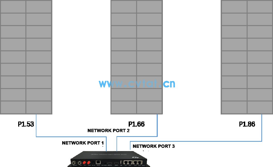
An exhibition hall uses three led displays of different LED modules to form a large screen. Each LED display is 2 modules wide and 9 modules high. It is connected with 3 receiving cards and 2 open output, and 4 network ports are used for output. The asynchronous playback box HD-A6 control, module information and connection diagram are as follows.


Module type    P1.53 26S    P1.66 32S    P1.86 43S    

Module size    320mm*160mm    320mm*160mm    320mm*160mm    

Module resolution    208*104    192*96    172*86    

Screen Resolution    416*936    384*864    344*774    

Chip information    ICN2055+2013    SM16259+2013    ICN2065+2018    

Control network port    network port 1    network port 2    network port 3    


Debug steps

Install HDPlayer software version 7.5.22.0, upgrade the control card to the corresponding firmware version, and upgrade the FPGA version to 0.8.0.0;

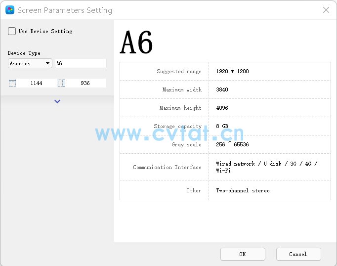
Set the screen parameters, the screen width is set to 1144 (ie 416+384+1144), and the height is set to 936;


Edit the program on the program editing interface and send it to the receiving card;

Upgrade the firmware of the receiving card (if the general firmware of the receiving card supports the modules of the above chips at the same time, it can be upgraded at one time, otherwise the corresponding firmware needs to be upgraded separately);

Open the HDSet software, select the new process to debug, debug the P1.53 display screen through the network port 1, and then solidify its parameters, that is, blindly input the receiving card parameters of the receiving card parameter interface cssd to lock the network port 1, and the number of receiving cards will be displayed. If it is 256, all receiving card parameters of network port 1 are successfully locked;


Use the same method to debug the display of P1.66 and P1.86 through network port 2 and network port 3 respectively.

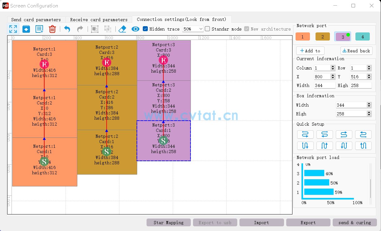
Enter the connection setting interface, set the resolution loaded by the receiving card of each network port and the connection sequence of the receiving card (you need to unlock the parameters of all network ports first), and then click Send to cure.


Play screen demo